Antenna selection is one of those decisions that gets treated as an afterthought in a surprising number of wireless system designs. Engineers spend months optimizing firmware, RF front ends, and protocol stacks, then specify whatever antenna is cheapest or most familiar at the end of the project. The consequence is usually discovered during field testing or, worse, after deployment — dead zones, range falling short of spec, interference problems that wouldn’t exist with a different antenna configuration.
The right antenna type depends on the specific application, the environment, the frequency band, and the form factor constraints. None of these factors can be treated in isolation. What follows is a practical framework for working through these decisions systematically rather than by intuition.
Start With the Radiation Pattern
The most fundamental characteristic of any antenna is its radiation pattern — the three-dimensional shape of how it distributes transmitted energy and receives incoming signals. Getting this wrong makes everything else irrelevant.
Omnidirectional antennas radiate energy roughly equally in all horizontal directions, with reduced radiation above and below. This makes them the right choice for applications where the location and direction of communicating devices is variable or unknown — access points serving mobile users, base stations for sensor networks, vehicular applications where the vehicle orientation changes. The trade-off is that the energy is spread across 360 degrees, which limits the gain achievable in any specific direction.
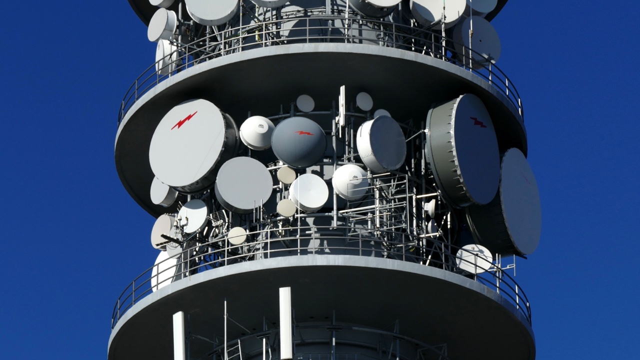
Directional antennas concentrate energy in a defined direction. This produces higher gain in the targeted direction, which translates to longer range for point-to-point links, better rejection of interference coming from other directions, and reduced interference caused to systems outside the beam. Yagi antennas, panel antennas, and parabolic dishes are all directional types with different beam widths and gain levels. The trade-off is that both ends of the link must be physically aimed at each other, which limits their use to fixed or well-characterized applications.
Sector antennas sit between omnidirectional and fully directional — they cover a defined angular sector (typically 60°, 90°, or 120°) with moderate gain. Three or four sector antennas can together cover 360° with better gain than a single omnidirectional, which is why they’re commonly seen on cellular base stations.
Match the Frequency Band
Antenna dimensions scale with wavelength, which scales inversely with frequency. A half-wave dipole at 433 MHz is about 34 cm long; at 2.4 GHz it’s about 6 cm; at 5.8 GHz it’s about 2.5 cm. This has direct implications for what’s physically feasible in your application.
Low-frequency bands (sub-1GHz: 433 MHz, 868 MHz, 915 MHz) propagate well through buildings and vegetation, making them suitable for long-range IoT applications, LPWAN networks, and applications where obstacles are unavoidable. Antennas at these frequencies are physically larger, which constrains miniaturization.
2.4 GHz is used by Wi-Fi (802.11b/g/n), Bluetooth, Zigbee, and several other protocols. It offers good indoor propagation with practical antenna sizes, and antennas in this band are widely available from a broad supplier base. The trade-off is congestion in dense RF environments.
5 GHz and above (including the 5.8 GHz band and Wi-Fi 6E’s 6 GHz additions) offer higher throughput and less congestion but attenuate more quickly through walls and over distance. They’re appropriate for applications where high bandwidth over short distances matters more than range.
Dual-band and multi-band antennas exist for applications that need to operate across multiple frequency ranges, but they involve compromises — no single antenna design can be fully optimized across widely separated frequency bands simultaneously.
Consider the Environment
The same antenna design performs differently in free space, indoors, in a vehicle, or mounted on a metal structure. Understanding the deployment environment is essential before finalizing antenna choice.
In indoor environments, multipath propagation — signals bouncing off walls, floors, ceilings, and furniture — can cause signal cancellation at specific locations. MIMO (multiple-input multiple-output) antenna configurations address this by using multiple antennas simultaneously and exploiting multipath rather than fighting it. Wi-Fi routers and access points have used MIMO for over a decade; the gain from 2x2 and 4x4 MIMO configurations in real-world indoor deployments is substantial.
In outdoor point-to-point applications with clear line of sight, high-gain directional antennas deliver the best performance. In outdoor non-line-of-sight environments, omnidirectional or low-gain directional antennas often outperform high-gain options because high-gain antennas have narrow elevation patterns that can miss signals arriving from unexpected angles.
Near metal structures — mounting antennas on equipment enclosures, vehicle bodies, or metal roofing — the metal surface affects the antenna’s radiation pattern and impedance. Antennas designed for this environment (ground-plane antennas, magnetic mount antennas with integral ground planes) account for this. Generic antennas mounted on metal without accounting for ground-plane effects will underperform against their datasheet specifications.
Connector and Cable Losses
An antenna’s performance at the end of a cable is always worse than the datasheet gain figure, which is measured at the antenna port. Coaxial cable attenuates signals, and the attenuation increases with frequency and cable length. At 2.4 GHz, standard RG58 cable loses roughly 0.5 dB per meter — a 3-meter cable between an access point and a remote antenna adds 1.5 dB of loss, which meaningfully reduces effective gain.
Low-loss cable types (LMR-400, LMR-240) reduce this attenuation but at higher cost and reduced flexibility. Connector losses at each join add further attenuation. The practical implication is that minimizing cable length between the radio and the antenna, and using the appropriate cable type for the frequency and application, is part of antenna system design rather than an afterthought.
Working with a knowledgeable Antennas Supplier who understands system-level performance — not just individual component specifications — helps avoid the common mistake of selecting a high-gain antenna and then losing its advantage to cable and connector losses that weren’t accounted for in the original design.
Practical Selection Checklist
Before finalizing an antenna selection, the relevant parameters to have confirmed are: frequency band and bandwidth required, radiation pattern needed for the application geometry, gain requirement based on link budget calculations, physical size and mounting constraints, environmental conditions (indoor/outdoor, temperature range, IP rating needed), connector type required, and whether the application needs single-band or multi-band coverage. Addressing all of these before procurement avoids the expensive iteration of discovering a mismatch after hardware has been designed around the wrong antenna.